By Fathalla Ramadan | March 2026 | Alexandria, Egypt
If you’ve ever wondered:
“How do I make my Packet Tracer lab talk to the ‘Internet’?”
You’re not alone. Many students assume they need complex setups or external tools. But Cisco Packet Tracer includes a built-in “Cloud” object that lets you simulate internet access—using just NAT and a single public IP.
This guide shows you how to give your internal network (e.g., HR, IT, Guests) full internet connectivity—just like in real homes and small businesses across Egypt, Saudi Arabia, and beyond.
✅ No GNS3
✅ No external servers
✅ 100% free, legal, and exam-aligned
Why This Matters
In the real world:
- Your ISP gives you one public IP (e.g., 203.0.113.10)
- All your devices share it using PAT (Port Address Translation)
- Internal IPs (like 192.168.x.x) are hidden from the internet
This is exactly what Cisco tests on the CCNA—and what employers expect you to configure.
What You’ll Build
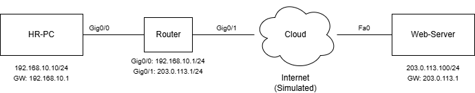
A simple topology with:
- 1x Internal LAN: PC (192.168.10.10/24)
- 1x Router: Performs NAT
- 1x Cloud: Represents the “Internet”
- 1x Web Server: Simulates a public website (203.0.113.100)
You’ll configure PAT (overload) so the PC can ping the web server—and appear to have a public IP.
Step 1: Build the Topology
- Open Cisco Packet Tracer
- Add:
- 1x PC (name:
HR-PC) - 1x Router (e.g.,
2911or4321) - 1x Cloud (from the “Network Devices” palette)
- 1x Server (name:
Web-Server)
- 1x PC (name:
- Connect:
HR-PC→Router(Gig0/0) via Copper Straight-ThroughRouter(Gig0/1) →Cloudvia Cloud-GigabitEthernetCloud→Web-Servervia Cloud-FastEthernet
Tip: Double-click the Cloud, go to Config → Ethernet, and enable the ports you’re using.
Step 2: Configure IP Addresses
On HR-PC:
- IP:
192.168.10.10 - Subnet:
255.255.255.0 - Gateway:
192.168.10.1
On Router:
enable
configure terminal
! Inside interface (LAN)
interface GigabitEthernet0/0
ip address 192.168.10.1 255.255.255.0
no shutdown
! Outside interface (to Cloud/Internet)
interface GigabitEthernet0/1
ip address 203.0.113.1 255.255.255.0
no shutdown
! Default route to “Internet”
ip route 0.0.0.0 0.0.0.0 GigabitEthernet0/1
On Web-Server:
- IP:
203.0.113.100 - Subnet:
255.255.255.0 - Gateway:
203.0.113.1
Note:
203.0.113.0/24is a reserved documentation range (RFC 5737)—perfect for labs.
Step 3: Configure NAT (PAT Overload)
On the Router, add:
! Define which internal traffic to translate
access-list 1 permit 192.168.10.0 0.0.0.255
! Enable PAT on the outside interface
ip nat inside source list 1 interface GigabitEthernet0/1 overload
! Mark interfaces as inside/outside
interface GigabitEthernet0/0
ip nat inside
interface GigabitEthernet0/1
ip nat outside
This is exactly the NAT config tested on CCNA.
Step 4: Test Internet Access
- On
HR-PC, open Command Prompt - Run: ping 203.0.113.100
- You should see replies!
- To verify NAT, on the Router, run: show ip nat translations
- You’ll see:
Pro Inside global Inside local Outside local Outside global
icmp 203.0.113.1:1 192.168.10.10:1 203.0.113.100:1 203.0.113.100:1
Success! Your private PC is now “on the internet.”
Common Mistakes & Fixes
| Issue | Likely Cause | Fix |
|---|---|---|
| Ping fails | Missing default route | Add ip route 0.0.0.0 0.0.0.0 <outside-int> |
| NAT not working | Forgot ip nat inside/outside | Apply to correct interfaces |
| Cloud not forwarding | Ports not enabled in Cloud config | Double-click Cloud → Config → Ethernet → Check ports |
Real-World Insight
In Egypt, most ISPs (like WE or Vodafone) give one public IP per household.
This exact NAT setup is used in every home and small business—making it essential knowledge for any network engineer.
Next Steps
Try these extensions:
- Add multiple VLANs (HR, IT) and NAT them all
- Simulate DNS lookup by adding a DNS server in the Cloud
- Block certain sites using ACLs before NAT
All of these are covered in Lab 4.1: NAT for Internet Access in my Lab Handout Book—with validation checklists so you know you’ve done it right.
Final Thought
You don’t need real internet to learn internet design.
With CCNA Hands-on lab free tools using Packet Tracer’s Cloud + NAT, you can simulate real-world connectivity—on any laptop, anywhere in the world.
And that’s the power of practical, accessible networking education.
Fathalla Ramadan
Network Architect & Educator | 35+ years across the Middle East & beyond
Author of IP Routing and Switching: A Practical Guide
Related: Free CCNA Checklist 2026 | CCNA Labs Bundle